Circuits
Circuits are pathways that allow electricity to flow through components like wires, switches, and bulbs. They can be simple, like a flashlight circuit, or complex, like those found in electronic devices. Understanding circuits helps us design and use electrical systems efficiently in everyday life.
Equations on this page:
Charge and Potential Difference (Ohm's Law)
Practicals on this page:
Investigating Resistance
Electric current, Potential Difference & Resistance
Electric current is the flow of electric charge through a conductor. Think of it like the flow of water in a pipe. In this analogy, electric charge is like the water, and the conductor (such as a wire) is like the pipe. Electric current is measured in amperes (A). An ammeter measures the current flowing through a wire.
Potential difference, often called voltage, is the energy transferred per unit charge as a charge moves between two points in an electrical circuit. It's like the "push" that drives the flow of electric charge through a circuit, similar to the pressure that pushes water through a pipe. Potential difference is measured in volts (V). A battery or power supply provides a potential difference across a circuit, causing electric charges to move through the circuit. A voltmeter measures the current flowing through a wire.
Resistance is a measure of how much a component or material opposes the flow of electric current. It's like the "narrowness" of a pipe in our water analogy. A narrow pipe would offer more resistance to water flow compared to a wider pipe. Resistance is measured in ohms Ω and it's represented by the symbol R.
Different materials have different resistances. For example, metals like copper have low resistance, while materials like rubber or plastic have high resistance. Resistance in a wire depends on factors like the material, length, thickness (cross-sectional area), and temperature of the wire.
What's the difference between Series and Parallel circuits?
In a series circuit, components (such as bulbs, resistors, or batteries) are connected one after the other in a single loop or pathway. The same current flows through each component in the circuit. It's like a line of people holding hands - they all move together at the same speed. If one component in a series circuit stops working or is removed, it breaks the circuit, and all components stop working because the circuit is broken at that point.
- Voltage: In a series circuit, the total voltage (potential difference) across the circuit is equal to the sum of the voltages across each component.
- Current: In a series circuit, the current is the same through all components.
- Resistance: In a series circuit, the total resistance is the sum of the resistances of each component.
In a parallel circuit, components are connected in multiple branches or pathways, with each component connected directly across the power source (like batteries). The current is split up among the branches of the circuit. It's like a road with multiple lanes - traffic (current) can flow through each lane independently. If one component in a parallel circuit stops working or is removed, the other components will continue to work because each branch of the circuit is separate from the others.
- Voltage: In a parallel circuit, the voltage across each component is the same as the total voltage supplied by the power source.
- Current: In a parallel circuit, the total current entering the circuit is equal to the sum of the currents in each branch.
- Resistance: In a parallel circuit, the total resistance decreases as more branches are added because resistance decreases with more paths for current to flow.
Revision Notes

The Cornell method is like a supercharged note-taking system that helps you ace your revision!
Print out our blank revision notes pages to help you revise.
How to make effective revision notes with the Cornell method.
Exam Questions & Answers

Download and print off practice our FREE worksheet with exam style questions on Cell Biology.
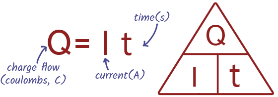
EQUATION - Charge
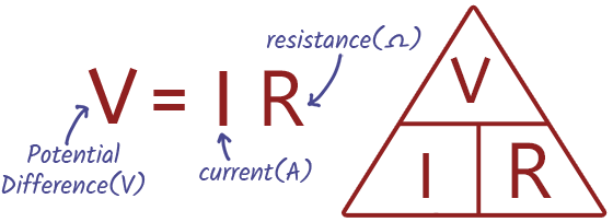
EQUATION - Potential Difference (Ohm's Law)
Potential difference can be calculated by using the current and resistance. This is also known as Ohm's Law which states that the current flowing through a conductor is directly proportional to the voltage applied across it, provided the temperature remains constant.

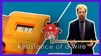
PRACTICAL - Investigating Resistance
- Set up a simple circuit consisting of a power supply (such as a battery), wires, a resistor (whose resistance you're investigating), and a variable resistor to control the current.
- Measure the voltage across the resistor using a voltmeter and the current passing through it using an ammeter.
- By changing the resistance of the variable resistor and recording corresponding voltage and current readings, you can plot a graph of voltage against current.
- Resistance can then be calculated using Ohm's law, which states that resistance equals voltage divided by current.
- Analyzing the gradient of the resulting graph helps determine the resistance of the resistor under investigation.
- Repeating the experiment with different values of resistance can provide data to verify Ohm's law and understand the relationship between voltage, current, and resistance in a circuit.
Revision Notes

The Cornell method is like a supercharged note-taking system that helps you ace your revision!
Print out our blank revision notes pages to help you revise.
How to make effective revision notes with the Cornell method.
Why Do I Need to Know About Circuits?
In Everyday Life
- Understanding how lights, phones, and home appliances are powered
- Knowing the difference between series and parallel circuits, so you can troubleshoot when a bulb or device stops working
- Grasping why fuses and circuit breakers are essential for safety — and why wire thickness matters
- Learning why voltage, current, and resistance affect how devices perform and how energy is used
- Recognising basic electrical safety, such as avoiding overloads and reducing the risk of shocks or short circuits
In Science & Physics Careers
- Designing and testing electronic systems for everyday technology—from smartphones to smart homes
- Building and repairing circuit boards, wearable electronics, and IoT devices
- Applying Ohm’s Law and other principles to create efficient power supplies, motors, and LED systems
- Working in engineering, robotics, or automotive industries, where circuit design and troubleshooting are essential
- Contributing to innovation in renewable energy, smart grids, and energy-efficient electrical equipment


